Riyas P.K-Fab Academy 2016
Embedded programming
The assignment for this week is to read a microcontroller data sheet and program our board (modified echo hello world) to do something, with as many different programming languages and programming environments as possible. I modified the design to make a circuit board with these features plus a pushbutton input and an LED output.There was some problems in my board,some of the traces were gone. So I milled another one.
Reading a microcontroller data sheet
I started out by getting a copy of the data sheet for the Atmel ATtiny 44a microcontroller. It is incredible that a $1 microcontroller has so many features that it takes 258 pages to explain. I found a lot of useful information but also found many details that I did not understand.
Data sheet highlights
- Since this assignment involves programming a pushbutton to control an LED, the information in section 10 (starting on page 52) was especially useful. It described how to configure, monitor, and control the inputs and outputs of the IC.
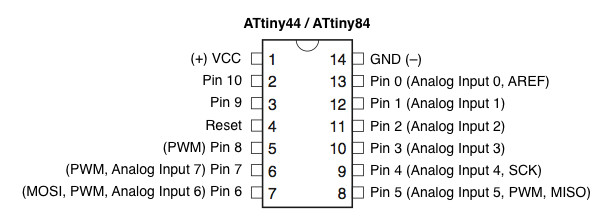
- When designing the circuit, I noticed how each chip pin was labeled with several abbreviations. For example, pin 13 is labeled PA0 (ADC0/AREF/PCINT0). Starting on page 59, the data sheet describes some of the alternate functions of the ports.
- A summary of the various registers with page references can be found on page 239.
- The instruction set summary is on pages 241 - 242.
Using Arduino 1.6.8 IDE to program the ATtiny on a 64-bit windows 10 computer
Since the programmer we using here (Atmel ICE) not working I used FabISP to program the board.
- I downloaded and installed the Arduino program.
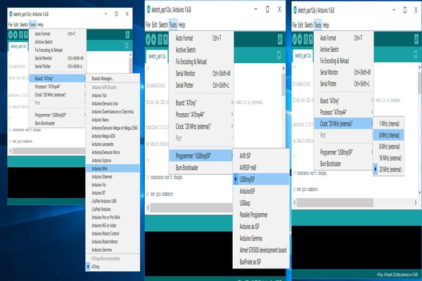
- I then downloaded a file called ATtiny_master.zip that contained information about the ATtiny chips. The folder attiny had to be added to a folder called hardware in the Arduino sketchbook location. Once I did this , I selected board, programmer, clock like in following screenshots.
- Connect the board with programmer (fabISP) using pin header and power it with FTDI cable
- Once it is done burn the bootloader, it can be done by Tools < Bootloader
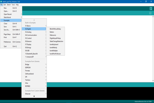
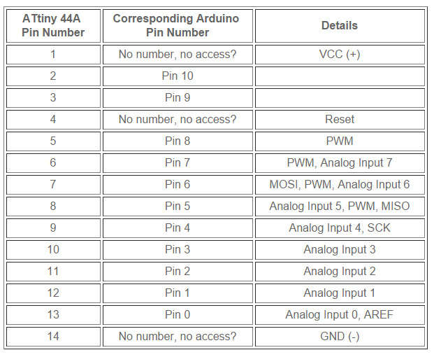
- Now we can program the board, for this select one of the examples in Arduino.I selected the button example for changing the code. Arduino uses different pins numbering than the ATtiny. So I had to consult a conversion chart to determine that my LED is connected to the ATiny44A pin 6 which is considered pin 7 on the Arduino and the pushbutton pin is 3 which is pin 9 on Adruino. After changing these press upload.
Program
             // constants won't change. They're used here to
            // set pin numbers:
           const int buttonPin = 3;     // the number of the pushbutton pin
           const int ledPin =  7;      // the number of the LED pin

           // variables will change:
           int buttonState = 0;         // variable for reading the pushbutton status

           void setup() {
           // initialize the LED pin as an output:
           pinMode(ledPin, OUTPUT);
           // initialize the pushbutton pin as an input:
           pinMode(buttonPin, INPUT);
           }

           void loop() {
           // read the state of the pushbutton value:
           buttonState = digitalRead(buttonPin);

            // check if the pushbutton is pressed.
           // if it is, the buttonState is HIGH:
           if (buttonState == HIGH) {
           // turn LED on:
          digitalWrite(ledPin, HIGH);
           }
           else {
           // turn LED off:
           digitalWrite(ledPin, LOW);
            }
          }
Result
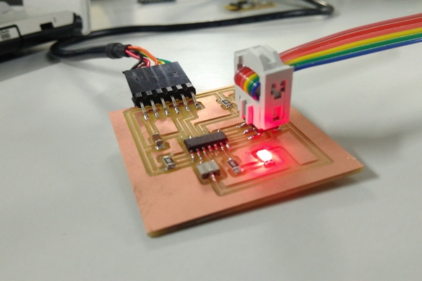
Like many AVR microcontrollers in arduino platform, attiny have internal pullup resistors.Pull-ups are often used with buttons and switches.Pull-up resistors will ensure that the pin is in either a high or low state(pull-down resistor).So instead of adding an external pull up resistor I could modify my board and use internal pull up resistor.for this you need to change code.For example : pinMode(5, INPUT_PULLUP); // Enable internal pull-up resistor on pin 5. This will enable a pull-up resistor in pin 5.
Update:
Recently, our instructor Fransisco pointed out that the method I used to add attiny boards to arduino is replaced by another method which is more simple and the pack is updated regularly.In this method the attiny board can be installed from arduino's built in board manager.For this got to Files->Preference, in this find the "Additional Boards Manager URLs" field near the bottom of the dialog box and paste the following URL to the field : https://raw.githubusercontent.com/damellis/attiny/ide-1.6.x-boards-manager/package_damellis_attiny_index.json.
Then click ok in the preference dialogue box.Now go to Tools->Board->Board manager,scroll down to bottom to find attiny listing.By clicking on it you can see the install option.Close the board manager, now you can see the listing of attiny in board menu.For a detailed description and othe useful tutorials visit : highlowtech.org
In case you are using arduino in ubuntu, the board managers option won't be availabe unless you installed it manually downloading and installing the tar.gz package from arduino site.
File
Download the file here: Button+LED.ino